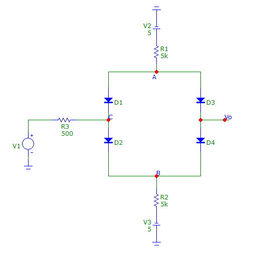
Here’s an practice problem with diodes that has some interesting aspects to it. This circuit is about as complicated as diode circuits get and performs a simple and potentially useful function. In other words, output voltage 

You should eventually build this circuit in SPICE, and perform DC or transient analysis to see what it does. But first, let’s use a simple ideal piecewise diode model to understand this circuit. If you are able to fully understand and explain the behavior of this circuit, you know everything you need to to know about diodes for the purposes of our class. For that reason, this is a good practice problem for your exam 1.
We will assume all 4 diodes are identical and have a constant voltage 
Because there are 4 diodes each of which can be on or off, there are as many as 
With a little bit of thought though, we can narrow this down quite substantially. Here’s a few hints. See if you can you explain why the following observations must hold:
- The voltage of node A cannot be greater than 5 V i.e.
. Likewise, we must have
. Note however, that there are no constraints on how low
, and how high
, can get.
- Node C cannot be at more than
above node B i.e.
.
- By the same reasoning
.
- If
and
are both off, then
. Similarly,
and
are both off, then
.
- The two previous observations show that it is not possible for all 4 diodes to be OFF at any time. Can you see why?
- By considering a small number of “corner cases” for extreme values of
- Case1: When
, we would expect
- Case 2: Can you repeat the reasoning from Case 1 for small
?
- Case 3: When
, purely by symmetry, we would expect
. What does this mean for the state of each of the diodes and the other node voltages?
