The modern theory of electronic communication, due to Claude Shannon, is famously abstract. It does not concern itself with the contents of the messages being exchanged, nor with the physics of how the information transfer takes place. From the source:
The fundamental problem of communication is that of reproducing at one point either exactly or approximately a message selected at another point.
In theory, this applies alike to communication using radio waves or smoke signals, or even to non-communication applications such as storing information on a magnetic tape. While this is beneficial in many ways, real-world communication engineering almost universally involves sending messages over electromagnetic waves. The actual practice of this engineering discipline will benefit a lot from some knowledge of the physics of EM waves.
Fortunately, this is a case where a little bit goes a long way. This series of short notes is intended to provide some very basic information about EM wave physics specifically tailored for comms engineers. The presentation is informal and simplified and aims to build a quick mental model to think intuitively about EM waves, rather than in-depth expertise. (Also, I have tried very hard to avoid any math! But don’t fret, there is no shortage of math in comm theory..)
Three types of comms links
Electronic comms systems have been built and used over a wide variety of physical media e.g. twisted-pair copper wiring, coax cable for CATV or computer networks, optical fiber and power-lines, in addition to wireless links over various frequency bands.
Fundamentally though, all of these media fall into one of just 3 categories: (a) metal wires, (b) wireless and (c) optical fiber. Each of these involve EM wave propagation, but the physical mechanisms are quite different and represent different special cases of the Maxwell equations (a vivid demonstration of the tremendous versatility of these equations..).
1. Communication over conducting wires.
This category includes most wired media used in modern comms except optical fiber, and is theoretically the simplest, and historically the first, type of media used for electronic communication. See e.g. this diagram of an early telegraph system (Sömmering’s electric telegraph in 1809, from Wikpedia.) 
For short link distances and slow signaling speeds, a metal wire acts like a short circuit; a voltage change at the transmitter instantaneously appears at the receiver. However, once the signaling speed becomes fast enough, it becomes necessary to account for the finite speed of signal propagation (which is approx 1 ft/ns in free space, slower in other media, but in the same order of magnitude).
Consider as a simple example, a telegraphy-like system sending symbols encoded as dots or dashes, by applying a short or long pulse at the transmitter once every T = 1 μ sec. If the link distance is longer than 1000 ft, the propagation delay over the link is longer than T; by the time the receiver sees a symbol, the sender is already transmitting a new symbol. The metal wire no longer behaves like a short circuit, not even approximately!
A signaling rate of one symbol every 1 μ sec requires a voltage waveform with a bandwidth of at least 1 MHz. An EM wave with a frequency of 1 MHz has a (free-space) wavelength of about 1000 ft, which is equal to the link distance in our example. This is a simple, easy and intuitive criterion to remember: current carrying metal wires no longer function like short circuits when the voltages in the circuit contain frequencies whose wavelengths are close to or shorter than the length of the wire.
Let us call this the corner frequency of the metal wire. Note that this corner frequency is a purely geometric quantity that depends only on the length of the wire and not on any material property of the wire. (For a specific frequency, the electrical length of a conducting wire is the length of the wire as a fraction of the wavelength. Thus, the corner frequency is defined as the frequency where the electric length of the wire is unity.)
In this regime, metal wires can be modeled as transmission lines i.e. a distributed network of series inductances and shunt capacitances that account respectively for the voltage and current variations over the length of the wire see e.g. (from Wikipedia):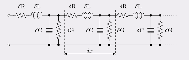
In addition, phenomena such as the skin effect mean we can no longer treat metal wires as near-lossless conductors (hence the R and G terms in the Heaviside model shown above). While it is possible to build useful RF and microwave circuits with metal wires functioning as transmission lines, their properties as a comms medium become severely degraded beyond these frequencies.
It turns out that the frequencies where metal wires stop functioning like short circuits are precisely the frequencies that we like to use for wireless comms. This is not a coincidence: when metal wires behave like short circuits, it is hard to turn them into antennas; conversely, we can build efficient antennas using conducting wires most efficiently when we are operating close to or above their corner frequencies.
Thus, there is a sweet spot in the EM spectrum with frequencies ranging from roughly 300 MHz (λ~1m) to 3 GHz (λ~10cm) that is best suited for wireless comms; waves much longer than this are hard to generate and detect and waves much shorter than this don’t propagate well. We will explore this in more detail in Part 2 of this series.

One thought on “Basic EM theory for comms engineers – Part 1: Metal Wires”