Modern electronic communication systems are usually designed to use passband signaling, i.e. the transmitted waveforms have their frequency spectra concentrated in a narrow range of frequencies around a carrier frequency. There are at least two excellent reasons for designing comms systems this way: (1) for fundamental physical reasons explored in another note, wireless links cannot be efficiently operated at low frequencies, and (2) this is a simple, effective and convenient multiplexing technique i.e. a method for multiple simultaneous transmissions to be sent over the same radio or wired link.
A Taxonomy of Passband Modulations
In textbooks and other resources, modulation methods are commonly presented in certain categories: analog v. digital; amplitude v. angle modulation and so on. A typical example is in this technical note from Rohm Semiconductor:
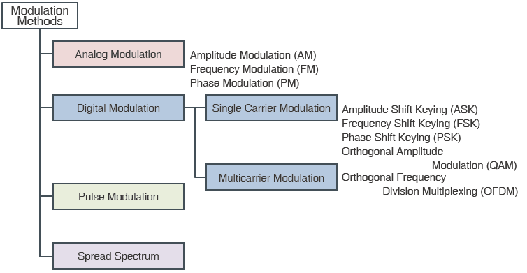
There are advantages to this classification system. It has some basis in the historical development of analog AM and FM. It also makes intuitive connections between digital and analog modulations e.g. ASK and FSK as natural digital variations on AM and FM respectively.
A Holistic Theory of Passband Modulation
In this note, we argue for a different way of thinking about modulations: the differences between all of the above kinds of modulations are superficial, unhelpful and ultimately unproductive; instead we should think of all passband modulations as special cases of one universal type of modulation: Quadrature Amplitude Modulation or QAM. To justify this perspective, we offer the following simple observations.
- Any passband signal x(t) can always be expressed in terms of a pair of baseband signals
(the I- and Q-components) relative to a carrier signal:
.
- The above representation is valid for any reasonable choice of carrier signal. In other words, the frequency and phase
of the carrier signal is somewhat arbitrary, but it makes sense to choose the frequency near the center of the passband to minimize the bandwidth of the resulting baseband signals.
- This means that we can always represent passband signals in terms of I- and Q-baseband components regardless of how it was originally generated. In particular, FM signals can be expressed in this way:
has the I- and Q-components:
.
- Note that the above is true of any reasonable FM signal; we do NOT limit ourselves to the special case of “narrowband” FM sometimes highlighted in textbooks where
and the AM connection is more obvious
.
- To phrase it crudely, FM is a special case of quadrature AM where the Q-component is chosen to make the envelope of the modulated signal constant over time!
- For digital modulations, PAM and PSK constellations are obviously geometric special cases of QAM and there is nothing to be gained in making artificial distinctions between them.
- At first sight, FSK seems to have distinct features: e.g. (a) an FSK modulated signal may be expected to show multiple distinct peaks on a spectrum analyzer, (b) unlike FSK, PSK and PAM may have discontinuities at symbol boundaries. However, these differences, if they are present, are signs of a poorly designed system. An FSK signal with multiple visually observable peaks represents an inefficient use of bandwidth, and pulse-shaping should eliminate any signal discontinuities in PSK, PAM or QAM signals.
A more reasonable distinction can be made between linearly modulated signals with geometrically simple QAM constellations and more complex modulations e.g. OFDM, but in all cases, it remains true that the information content in a passband signal can be expressed in terms of baseband I- and Q-components or their samples.
